Star 45

Star 45

Saturday, December 23, 2006

S45 Construction | John Fisher - keel tubes

Date: Fri, 22 Dec 2006 18:22:14 -0700 (Mountain Standard Time)
From: "John Fisher"
To: "Dave mainwaring"
Subject: Star 45 keel tubes


Here is a photo sequence showing how I made my keel tubes. I am using a keel from CPM (David Ramos) with longer keel bolts so they will go through the deck when finished. I coated the brass rod with carnuba was as a mold release.

http://woodstar45.blogspot.com/2006/10/s45-construction-john-fisher-keel.html

John

Radio install on star # 3 | John Fisher

http://woodstar45.blogspot.com/2006/10/s45-model-boat-construction-sail.html

Date: Fri, 22 Dec 2006 18:09:14 -0700 (Mountain Standard Time)
From: "John Fisher"
To: "Dave Mainwaring" ,
Subject: Radio install on star # 3


Here are a couple of photo's of my latest star. I have just finished installing the radio tray for an under deck winch, jib tweaker, and rudder servo. I also included a photo of the sheet through deck mount. I also show the jib tweaker turn around. The part is a 180 deg sheet lead from great basin.

The radio tray is 1/16 ply backed up with 1/8 X 3/8 spruce or basswood. Note the glassing at the ends. This adds a lot of strength to the joint and I highly recommend adding it. I have 1" wide glass tape that I cut in half, then sprayed with 3M77 so it will stay in place for gluing. Then a dab of your favorite epoxy and you are done.

Thursday, December 21, 2006

Duddy's universal building jig,: materials used


From: "MICHAEL DUDDY"
M. Duddy's universal building jig
Date: Thu, 21 Dec 2006 08:28:46 -0500


The material used in the jig is 1"x1"x1/16" aluminum square tube( very ridged and no twist).
The ends are 1 1/2" angle bolted in two places on the ends as you can see in the pictures. I checked the ends with levels and the jig is dead straight.

The angle pieces with the screws in them are 3/4"x 1/16" x 6" long. You mount your frames to these with a square on the centerline of your frame inline with the center of the attachment piece.

Next you use a square to square these on the jig rails, and line up with the string. Now you are rite on brother.:) The dimensions of this jig are ; 60" long x 6" wide because they only had 60" pieces in the rack , and I didn't know what I might be building in the future. You can make it any size you want.

The end plates I made from 1/4"(stuff laying around), and milled slots in them so I could slide the jig to one side or the other for balance. If you have any questions or if I can help you in any way , get in touch with me.

Mike

Tuesday, December 19, 2006

S45 Construction Michael Duddy's Universal Building Jig


From: "MICHAEL DUDDY"
Subject: universal building jig
Date: Mon, 18 Dec 2006


Attached is the pictures of the jig. It isn't hard to build , and can be used on most any boat model (maybe even wings too). It is all adjustable , and it can be tilted on either side to plank the sides of the hull you are working on. Once the hull is done it can be removed very easy. The materials are available at places like Home Depot,or Lowes , and I know of some aluminum suppliers that sell in small quantities. I could draw up some plans if anyone is interested. I have to make a stem and transom angle holder for it.


Join the AMYA Star45 Class !

Sunday, December 17, 2006

Tank Notes on International Star Boats (1/3 size models)

Tank Notes on Star Boats: "ROUND chines add another complication to getting speed from a hull. This bad feature is an extension of the range in which burble will appear. In the wake of any transom-sterned boat, a severe agitation of the water may be noticed, an indication that a breakdown is occurring in the flow of water under the boat. When water is released from the transom properly, the burble that means an increase in resistance is not present. However, it is possible to run without burble only above and below definite speeds, the range depending on the lines of the boat. But, also, the shape of the chine has some effect. With a square-chined Star, it is safe to say that the burble will appear at about 5 knots and run clear aft at about 6 1/2 knots (when the boat is upright and on the designed trim). Increasing the bilge radius to 3 inches, on a Star, increases the burble range by dropping the lower limit to 4 1/2 knots and by raising the upper limit to 7 1/2 knots. Also, a model with round chines, when running heeled, begins to climb out of the water forward as the speed increases, the round chine acting as a flat surface on which the model tries to plane. To complete the analysis, it is necessary to go back to sharp-chined heeled models, in which the burble range is from 4 1/2 to 6 1/2 knots.

With the sharp-chined models, there was no indication that the bow tried to rise, a further proof that the sharp entrance angles are imperative. The easiest way to decrease the burble range is to trim the boat by the head and, conversely, the handicap of a trim by the stern is that it will cause the water to break away from the transom at speeds lower than normal. Under all conditions except that of a rounded chine, the burble range increases by dropping the lower limit; the upper limit is quite constant, being 6 1/2 knots. Interestingly, that is approximately the speed at which some styles of Star hulls show the first signs of planing.

In summary, it can be said that many Star boat owners might have had a faster boat than the standard Star because:
1. The fore and aft contour of the boat had been flattened and a large decrease in resistance accrued.
2. The boat was sailed down by the head, at least while running, which would give a 12 per cent decrease in the power required to drive her.
3. Square chines might have been used, which mean a decrease in resistance.

Although this work was done directly on Stars, the information is also applicable to other types of square-chined boats. But it must always be remembered that, even though a skipper have all the information in the world and his boat has an enviable heritage from designer and builder, the combination must sail hard to be a winner."


Complete article on www.starclass.org/

Tuesday, December 05, 2006

Star 45 Class | Rod Carr's "SPOT" Star #1


The modern day Star 45 Class got started back "when" Rod Carr got the AMYA launched and introduced the modeling world to his Star #1

Saturday, December 02, 2006

7.0 KEELS AND BALLAST BULBS: class specs.

Class specifications as of 2006:

7.0 KEELS AND BALLAST BULBS:

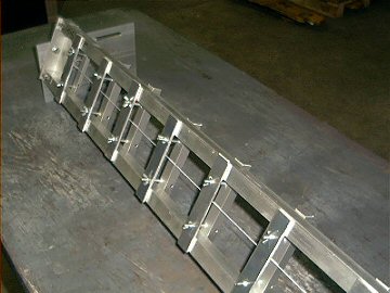
7.1 Keel will be of the style known as drop, and will be of the FIN and BULB type.

7.2 Keel fins may be solid or hollow and constructed of reinforced plastic, plastic laminates, fiberglass, wood or metal. (Note: Strength and integrity of the keel fins must be maintained whether built solid or hollow.) Keel fin shape is not specified but must follow the general shapes outlined on the reference drawing. However, keels will not be less than 6 inches nor more than 8 inches long (Fore and Aft) at the keel/hull junction, nor less than 4 inches nor more than 6 inches long (Fore and
Aft) at the keel/ballast bulb junction.

7.3 Keels, keel fins and ballast bulbs may be removable, however, they may not be changed, interchanged, substituted or otherwise manipulated once any heat or series of heats in which scores will be compiled, has started. Mechanically movable keels or ballast bulbs are specifically prohibited from use in Star 45 Class Yachts.

7.4 Ballast bulbs may be constructed of any material not prohibited by the AMYA. The actual shape is left to the builder's discretion, but will not exceed 9.75 (9 3/4) inches from the front of the keel bulb to the rearmost point of the keel or bulb.

7.5 Total drop (length) of the keel fin/ballast bulb combination will not exceed 11.5 (11 1/2) inches when measured from the keel/hull junction, before any fillers or streamlining is added.

7.6 Ballast may be made from any readily available material, such as poured lead, lead shot, etc. (Note: When using material such as lead shot, the mass must be solidified through the use of a bonding agent such as fiberglass or epoxy resin, plaster of paris, poured over and through in order to create a solid mass.)

7.7 Race directors may elect to use a template based on the construction plans to determine the keel length (depth).

7.8 Keel depth shall be measured from the center of the keel fin at the hull to the bottom of the ballast bulb. This measurement is from the edge of the bottom of the hull as it meets the side of the keel and should be determined during construction and before any fillet or fairing is added.

7.9 The Star 45 Class specifically excludes radio equipment, sail controls and batteries (power cells) from being considered ballast. This specification defines ballast as anything carried aboard the model for the main purpose of changing the weight distribution of the model and/or weight of the model. Ballast shall be fixed in place by gluing, fiberglassing, or bolting (bolts and screws).

7.9.1 Ballast may not be removed or relocated during any one regatta. The use of Velcro or similar quick release fasteners is prohibited as methods of mounting ballast.